
Extruded profile geometry and installation review
Custom silicone profile projects start with the cross-section. The drawing, groove condition, bend path and cut length decide whether the extrusion can hold its shape and fit the final installation.
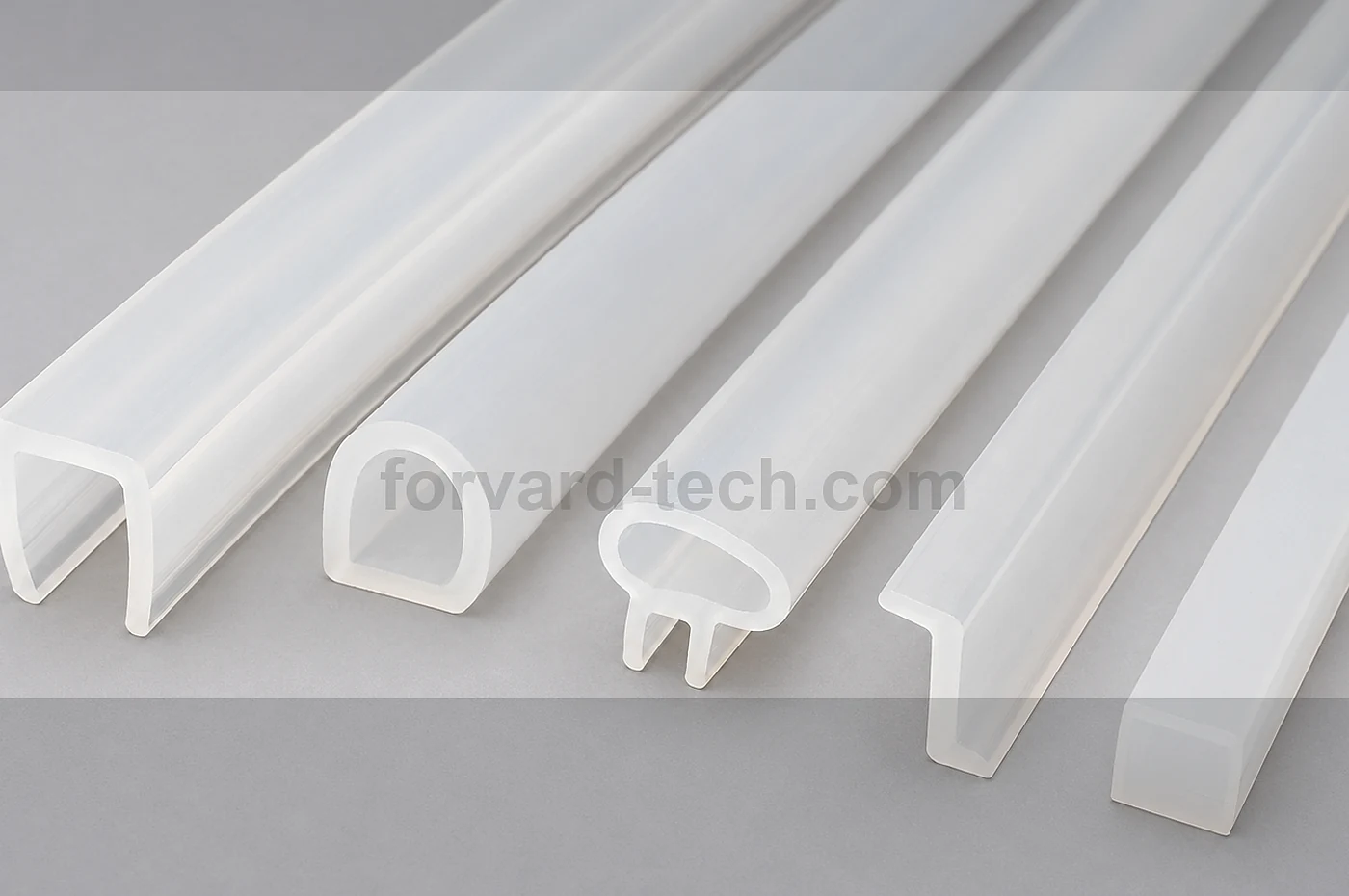
Product Fit
For projects that require a continuous or cut-to-length silicone profile with reviewed cross-section, wall thickness, and production details.
Cross-section control
Wall thickness, hollow areas, lips and sealing edges must be clear before extrusion feasibility can be reviewed.
Installation path
Straight runs, bends, corners and frame joints affect material hardness, profile stability and packing method.
Cut or splice requirement
The project may need plain cut lengths, miter cuts, adhesive joints or vulcanized frames depending on assembly needs.
Engineering Review Inputs
A profile RFQ should make the section shape and installation route visible.
- 2D cross-section drawing with critical dimensions marked
- Target hardness, color and material family if already defined
- Cut length, length tolerance and expected annual quantity
- Groove, channel, frame or mating surface details
- Corner, splice, adhesive or vulcanized joint requirement
- Packing form: coils, cut bundles, labeled kits or protected frame packing
Manufacturing Route
Extrusion review connects section design with die work, curing, cutting and post-process handling.
Die and trial route
The extrusion die is checked against critical lips, thin walls and areas that may swell or collapse during curing.
Cutting and joining
Cut length, corner treatment and joining method are reviewed before samples move toward repeat production.
Packing protection
Long profiles and frames need packing that avoids deformation, dust pickup and mixed-length confusion.
DFM / Tolerance Review
- Separate sealing dimensions from reference dimensions on the drawing.
- Avoid unsupported thin lips unless the mating groove and compression are clear.
- Frame joints should identify corner radius, joint location and acceptable appearance.
Testing / QC Boundaries
- Cross-section, hardness, cut length and visual condition can be checked against the approved drawing.
- Compression or aging checks need a method, temperature and time condition agreed before sampling.
- Document requests are reviewed by material, batch and destination instead of being promised for every profile.
RFQ Parameters
For custom profiles, send the section drawing and installation context before asking for tooling or sample timing.
Profile feasibility is confirmed by extrusion trial, material route, tolerance target and project quantity; published text is not a tooling-cost, lead-time or performance commitment.
- Cross-section drawing
- Material hardness and color
- Cut length or frame size
- Installation groove or mating surface
- Joint and packing requirement
Related Products
These pages help when an extrusion request becomes a gasket, molded part or compression-set review.