
Die-cut pad and assembly stack-up review
Thermal pad projects become practical when the buyer can describe the actual gap, pad outline, liner preference and assembly pressure instead of only asking for a catalog thickness.
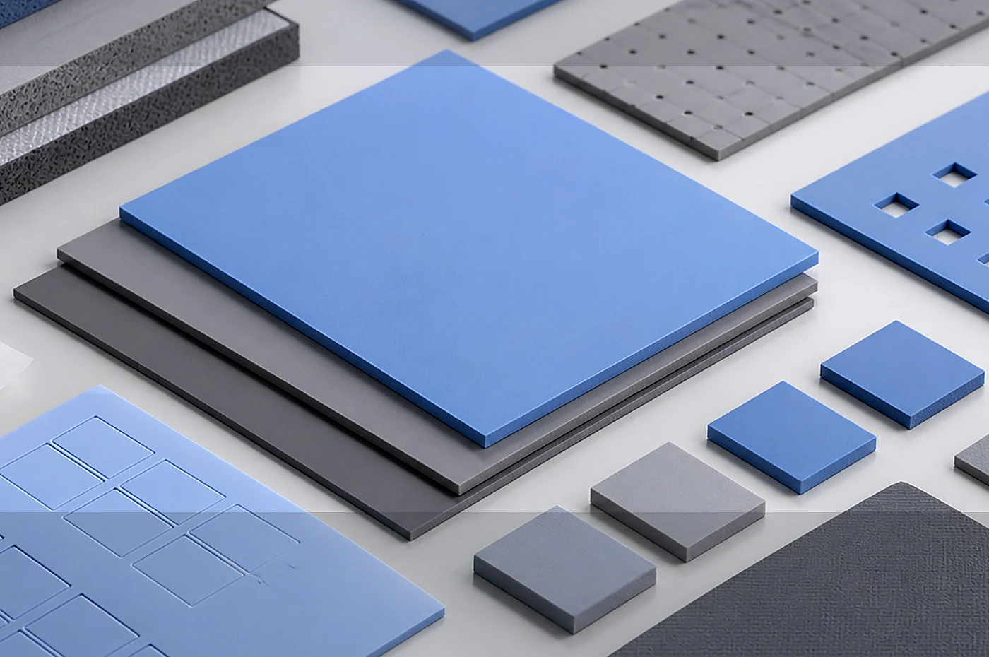
Product Fit
For projects that require a controlled pad, sheet-cut part, or assembly kit with defined geometry and application details.
Defined pad outline
A drawing-led pad can include holes, slots, edge clearances, liner orientation and part separation needs.
Known gap range
The nominal gap and tolerance stack decide whether the pad can maintain contact without overstressing the assembly.
Line handling
Pads may need liner tabs, sheet format, trays or bagging so operators can place them cleanly and repeatably.
Engineering Review Inputs
Thermal pad quotation depends on both material choice and conversion details.
If the drawing is not yet fixed as a finished pad, start with a thermal silicone materials review first. That step checks the sheet, compound, compression and insulation boundary before the project moves into liner, adhesive, die-cutting and packing details for thermal pads.
- 2D pad drawing, CAD file or marked dimension sketch
- Nominal thickness, tolerance expectation and gap range
- Compression percentage or assembly pressure limit
- Liner, adhesive, surface tack and release direction preference
- Hole, slot, kiss-cut, sheet layout or individual-piece packing requirement
- Thermal, dielectric, aging or customer validation method if already defined
Manufacturing Route
Pad production is checked as a conversion job: sheet choice, liner direction, cutting method and packing format must match the drawing and the assembly line.
Material and liner selection
Sheet grade, liner type and handling surface are chosen before tool or cutting review.
Die cutting or plotter cutting
Prototype pads may use flexible cutting, while repeat production normally needs a clearer tooling and nesting plan.
Packing control
Pads can be packed on sheet, in separated pieces, or in trays depending on tack, thickness and assembly workflow.
DFM / Tolerance Review
- Small bridges, narrow slots and unsupported holes need tolerance review before tooling.
- If tack is required, define which side contacts the component and which side releases first.
- Pad compression should be checked against screw force, housing flatness and component load limits.
Testing / QC Boundaries
- Thickness and outline inspection can be tied to the released drawing.
- Thermal or dielectric evidence is reviewed when the customer specifies method and acceptance boundary.
- Packing inspection should confirm liner orientation, part count and visible contamination control.
RFQ Parameters
For thermal pads, the fastest review starts with a drawing, target thickness and a clear note about how operators will pick, release and place the part.
Thermal pad feasibility is confirmed against drawing revision, material, quantity stage and validation method; no website text should be read as a price, delivery or test-result guarantee.
- Pad drawing with revision
- Thickness and tolerance
- Gap and compression range
- Liner or adhesive preference
- Packing format and quantity stage
Related Products
Related product pages can help compare thermal interface material options, soft gap filling requirements, and RFQ documentation needs before review.