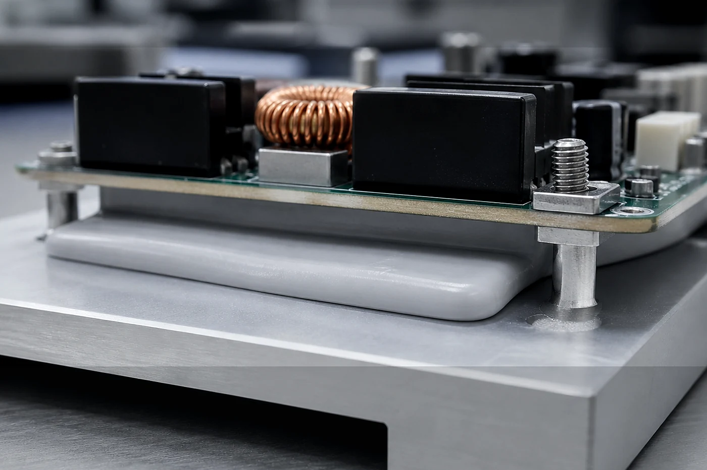
A3 · Part type
Silicone Gap Fillers for Uneven Thermal Interfaces
Low-modulus silicone gap filler review for assemblies with uneven surfaces, compression limits and thermal path targets.


Typical project fit
Specifications, documents and acceptance are confirmed by project details rather than by page content alone.
- Custom-form gap filling parts
- Electronics and industrial assemblies
- Applications needing sample validation before production

Geometry review
Shape, dimensions, tolerance and application conditions are reviewed before sampling or production.

Production context
Real facility photos support capability proof without making fixed stock, lead-time or performance promises.
project details to prepare
- Gap range and installation location
- Compression, tolerance and assembly constraints
- Required tests or customer validation steps
- Shipping country or region
- industrial application note
Process Routes
Gap fillers are built around low-modulus silicone formulations that can compress into uneven spaces without creating excessive assembly load. The material is typically cast to controlled thickness and then kiss-cut, sheeted or waterjet-cut depending on geometry. The soft feel, compression recovery and surface tack come from formulation and sheet process choices, not from a simple post-treatment after cutting.
During process review we look at gap size, stack-up tolerance, pressure available in the assembly, surface condition, liner handling and whether the part must stay in place before final assembly. Gap filler selection often balances thermal path, compression behavior and handling. A part that is easy to place manually may not behave the same way in an automated assembly flow, so the RFQ should explain how the customer plans to install it.
Testing Boundaries
Testing boundaries for gap fillers usually include compressibility, compression set, surface tack, thickness consistency and thermal behavior compared with compression. Buyers may ask for a curve showing how the material behaves under assembly pressure, or a review of whether thermal performance is stable after cycling and aging.
We treat these tests as project-specific discussions. A gap filler result depends on formulation, thickness, compression condition, fixture method and aging plan. If the assembly has a defined pressure window, include that condition in the RFQ so the validation path can be discussed. All testing is project-specific and confirmed during drawing review. Not a blanket capability guarantee. See our Testing and Quality Control page for the broader review workflow.
Application Fit
Gap fillers fit assemblies where surfaces are uneven, the thermal path is not flat, or the available space changes across the stack. Typical civilian industrial uses include large-gap interfaces, multi-layer PCB stack heat spreading, battery module thermal management, power converters, control units and enclosures that need a compliant thermal path.
If the interface is thin, flat and better suited to die-cut sheet handling, review thermal silicone pads for die-cut assembly. If a thermal assembly also needs custom molded geometry around bosses, holes or ribs, review molded silicone parts for OEM components as a separate route.
Engineering Review Notes
A gap filler RFQ is usually driven by assembly variation. The part must compress enough to contact uneven surfaces while avoiding excessive load on boards, housings or modules. Because the material is intentionally soft, drawing review must include how the part will be handled before assembly. A gap filler that works in a lab sample can still be difficult to place if liner, tack and packaging are not reviewed.
Compression behavior should be discussed with the real stack-up. Nominal gap alone is not enough because the maximum and minimum assembly conditions determine whether the material is under-compressed, over-compressed or difficult to install. We review the gap description, pressure expectation, surface roughness and installation sequence before recommending a sheet route, cut route or packaging format.
Surface tack is a formulation and handling decision. High tack can help placement, but it can also complicate release liner removal, automated placement or rework. Non-tack surfaces can be easier to handle but may require another method to keep the part located during assembly. The RFQ should state whether temporary positioning, clean removal or repeated handling is important.
Validation often combines compression, thermal behavior and aging. The result depends on formulation, thickness, compression state and test method. We can help prepare a validation plan, but the buyer should define what the assembly must prove. The review is strongest when the customer shares the mechanical stack-up and the thermal path requirement together.
Drawing Questions to Resolve
- What are the nominal, minimum and maximum gap conditions?
- How much assembly pressure is available without damaging nearby parts?
- Does the material need tack, non-tack surface, liner or carrier film?
- Will operators place the part manually or through a fixture or automated process?
- Which thermal or compression condition is used for internal validation?
- Does the final product require aging, cycling or dimensional review before approval?
Supplier Coordination and Approval Path
Supplier coordination for gap fillers starts with compression and handling review. Because the part is soft by design, we look at whether operators can place it, whether liner removal is stable, and whether the material can survive shipping and storage before assembly. These factors are often as important as the thermal path itself.
Sampling should be planned around the real stack-up. A buyer may need several material softness directions or surface conditions before the assembly team confirms what can be installed consistently. We prefer to review that plan before quotation so the sample package is useful rather than only visually similar to the requested shape.
Production review includes sheet control, cut method, liner format, packaging and surface protection. A very soft gap filler can deform if packaging is not matched to part size and handling method. The production route should therefore be reviewed together with the customer’s incoming inspection and storage condition.
Document review is project-specific. If the final product needs material statements, aging data, internal validation support or third-party lab coordination, that scope should be requested during RFQ review. We avoid broad site-wide claims because gap filler behavior depends strongly on formulation, thickness and compression condition.
A practical approval path is stack-up review, material screening, sample handling review, assembly feedback, quotation update and production release. When purchasing and engineering share the same gap condition and pressure assumptions, the project is less likely to cycle through avoidable sample revisions.
Revision Control and Scale-Up Notes
Revision control for gap fillers should track material softness, surface tack, liner format, thickness target, part outline and compression assumption. A small change in handling or liner can affect installation even when the visible part outline stays the same.
Scale-up review checks whether the sample can be packaged, shipped and placed consistently at pilot or production quantity. Very soft materials may need trays, carrier film or operator instructions that are not obvious from the first prototype request.
If the project moves from hand placement to fixture or automated placement, the gap filler may need another review. The quotation should then revisit tack, liner release, packaging and incoming inspection so production handling matches the actual assembly line.
Customer feedback should separate thermal result, compression fit and handling feedback. Combining all feedback into a single approval note can hide the real reason for a revision. Clear feedback lets the next sample target the right part of the design.
Before production release, the buyer should confirm whether the approved sample represents final thickness, final surface condition and final packaging. This protects both sides from approving a lab sample that is not practical for recurring production.
Production Release Check
Before production release, the buyer and supplier should confirm the approved drawing revision, material route, sample reference, inspection scope, packaging method and target market document needs. This keeps quotation, engineering review and production control connected to the same project basis.
For custom silicone parts, approval is not only a purchase order step. It is a technical handoff from RFQ review to sampling, then from sampling to repeatable production. Any change in drawing, material, quantity stage, validation method or destination should be reviewed before it becomes a production assumption.
Incoming inspection should also be agreed in practical terms. Some projects focus on dimensions, some on appearance, some on compression behavior, and some on document traceability. Stating the priority before production reduces disputes and makes the acceptance process easier for both procurement and engineering teams.
If the customer later changes the assembly, operating environment or validation method, the approved silicone part should be reviewed again. This review does not imply a blanket promise; it is a project-specific control step that protects the buyer, the supplier and the final industrial application.
DFM and Tolerance Review
For gap filler DFM, we review whether the part can be handled without stretching, tearing or losing placement accuracy. Very soft materials may need liners, carrier film, larger handling tabs or a packaging plan that protects the surface before assembly.
Tolerance review is based on thickness, compression condition, sheet process, cutting route and measurement method. We do not present a general tolerance promise on the website. Mark any critical gap or contact area in the drawing or stack-up sketch so it can be reviewed before sampling.
Our DFM review supports manufacturability discussion for silicone parts. It does not replace the customer’s product design responsibility, final application validation, regulatory approval, or certified engineering design service.
What to Prepare for RFQ
- Gap size and stack-up condition
- Available assembly pressure or compression target
- Thermal path requirement without fixed website performance assumptions
- Surface tack, liner and handling preference
- Part outline, installation method and quantity stage
- Compression, thermal, aging or dimensional validation request
- Destination market for document review
Request Engineering Review
Send your drawing, target material and application details for a project-specific quotation. Every request is reviewed individually after drawing and requirement review. We do not auto-quote, and we do not make blanket performance or certification promises before the project scope is understood.
RFQ Parameters
The values below are indicative material-family references for RFQ discussion, not final product specifications or blanket performance promises. Final thermal conductivity, hardness, thickness, compression behavior, temperature range and documentation scope must be reviewed by material grade, drawing, sample condition and test method.
| Parameter | How to Specify in RFQ |
|---|---|
| Gap size | Nominal and maximum/minimum gap |
| Stack-up condition | Assembly pressure and tolerance stack |
| Thermal conductivity target | Target W/m·K, if defined |
| Compressibility | Softness and compression requirement |
| Surface condition | Tack / non-tack / liner / adhesive |
| Electrical insulation | Required or not required |
| Application | Power module, enclosure, heat sink, control unit, etc. |
| Validation request | Compression, thermal, dimensional or aging review |
Common Material Options for Review
The values below are indicative, not final specifications.
| Material Family / Filler Type | Typical k Range (W/m·K) | Typical Hardness Direction | Common Use | Notes |
|---|---|---|---|---|
| General thermally conductive silicone | Project-specific | Soft to medium | Industrial electronics, enclosures | Final grade reviewed by drawing and stack-up |
| Alumina-filled silicone | Typical low-to-mid range | Shore 00 / Shore A by grade | General thermal interface use | Confirm with material grade |
| Boron nitride-filled silicone | Typical mid-to-higher range | Grade-dependent | Higher thermal performance requests | Reviewed by compression and dielectric needs |
| High-performance filled silicone | Project-specific | Grade-dependent | Power modules, demanding thermal paths | Requires application and test review |
Cost Factors
Custom silicone parts have project-specific pricing. The main cost factors depend on your drawing, material, tolerance, tooling route and quantity. For a detailed explanation, see our Pricing Factors page.
For gap fillers, additional cost factors include:
- Compressibility and softness requirements
- Surface tack or non-tack selection
- Gap tolerance and stack-up condition
- Testing requirements (compression set, thermal cycling)