
Tooling, geometry and molded-part review
Molded silicone part review begins with geometry. Undercuts, wall thickness, parting direction, inserts and inspection points decide whether the project can move from drawing to tooling.
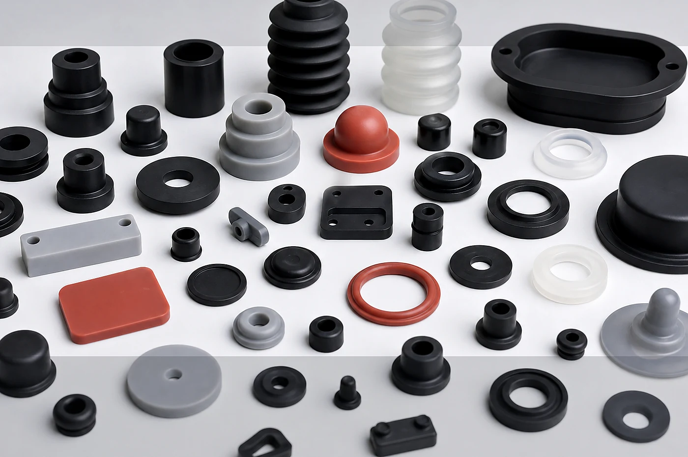
Product Fit
For three-dimensional silicone components where geometry, tooling approach, material choice, and production details need joint review.
3D geometry
Bosses, ribs, lips, pockets and complex corners require tooling direction and demolding review.
Functional surfaces
Sealing faces, touch surfaces, holes and insert areas should be marked separately from non-critical cosmetic zones.
Prototype to tooling
Early samples may verify form and assembly before final mold decisions are locked.
Engineering Review Inputs
A molded-part RFQ needs enough geometry detail to check tooling risk before price discussion.
- 2D drawing, 3D model or physical sample with measured critical areas
- Material family, hardness, color and surface finish expectation
- Critical dimensions, tolerance class and inspection datum
- Insert, bonding, overmolding or post-processing requirement
- Expected sample quantity, production quantity and packaging method
- Application environment, contact media and operating temperature range
Manufacturing Route
Molding review ties geometry to tool design, material flow, demolding and inspection.
Tooling direction
Parting line, gate area and demolding path are checked against visible surfaces and functional edges.
Material and curing
Hardness, tear resistance, compression behavior and surface finish are considered before sampling.
Post-process handling
Trimming, deflashing, inspection and packing are planned around the part geometry and customer use case.
DFM / Tolerance Review
- Mark critical dimensions so inspection does not focus on non-functional surfaces.
- Avoid sharp internal corners where material flow or demolding may become unstable.
- Clarify insert retention or bonding needs before mold design starts.
Testing / QC Boundaries
- Dimensional inspection can use drawing datums and agreed critical features.
- Hardness, appearance and trimming condition are checked by material and part form.
- Performance or compliance documents require project-specific method and batch scope.
RFQ Parameters
For molded parts, send the drawing package and mark the surfaces that control fit, sealing or assembly.
Molded-part review is tied to final geometry, tooling plan, material and batch; the site does not guarantee tooling cost, sample timing, inventory or test outcome.
- 2D drawing or 3D file
- Critical dimensions and tolerance
- Material hardness and color
- Functional surfaces or sealing areas
- Sample and production quantity
Related Products
These paths fit projects that may shift between molding, profile extrusion or sealing geometry work.